Use the Rotate tool to rotate the current object.
|
|
![]()

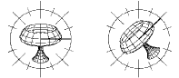
Example of rotation of part of an object
![]()
This tool can use the Dynamic Geometry properties. For more information, see the chapter User Manual/ The Objects/ Dynamic Geometry.
q Rotate an object by a given angle.
Usage:
1. Selecting the element or the part of the element you want to rotate.
Using the Wand, click on the element you wish to rotate.
Use the Lasso or the Bullseye to rotate part of the object. (See chapter User Manual/Modeling help tools/Assistant Palette/Selection Tools).
2. Selecting the Rotate tool.
Click on the icon depicting the Rotate tool in the Tools Palette.
A circle appears around the element or around the selected part of the element.
3. Dynamic Geometry properties.
Depending on how you created the current object, you can work with its Dynamic Geometry properties. This means that you can work on one of the following four finishing levels:
1 – Rough structure
2 – Smoothed structure
3 – Rough object
4 – Smoothed object
In the “Dynamic Geometry” palette, click on the icon depicting the finishing level on which you want to work.
![]()
If you decide to work on your model at finishing level “n”, then you will no longer be able to work on levels “1” to “n-1” (the icon of the disabled levels will disappear).
![]()
For more information, see the chapter User Manual/ The Objects / Dynamic Geometry.
4. Changing the plane of rotation.
You can change the plane of rotation. Use the arrow keys of the numeric keypad to change the plane. (See chapter User Manual/ Modeling help tools/ Control Panel/ Views).
The circle of rotation is displayed on the selected plane.
The axis of rotation is always perpendicular to the plane of rotation.
5. Defining the center of rotation.
The center of rotation is set by default on the center of geometry of the element.
It is identified by the following icon: ![]()
You can define a different center of rotation:
· 1st method: Click on the corresponding icon in the Assistant Palette.
· 2nd method:
· On PC: Click the right mouse button.
Or
· On Mac: Click the mouse button and simultaneously press the Option key.
The cursor switches to the following shape: ![]()
Click on the new position. The center of rotation will be set on the closest existing point of the scene.
6. Setting the rotation increment value.
You can increase or decrease the rotation increment of the circle of rotation either through:
· The “+” and “-” keys of the numeric keypad.
· The “+” or “-” buttons of the Assistant Palette.
7. Doing the rotation.
There are three ways to rotate an object:
· Mouse clicks
· Click on the edge of the circle to set the starting point of the rotation.
![]()
Clicking outside or inside the circle of rotation will re-scale the circle: the circle of rotation will change radius to include the specified point. This is only for your viewing convenience and has no effect on the operation of the tool.
· Drag the cursor in the right direction, checking the angle value displayed in the data window.
· Click when satisfied.
· Entering a precise rotation angle value
· Press the Tab key.
· Enter the rotation angle value.
· Press the Return key to validate.
· Using the “Remote Control”
The Remote Control is used to remotely fine tune an operation.
· Press Ctrl+Shift+Arrow key. (See chapter User Manual/Tools/The Data Window/ Numerical data/ Modifying a numerical value/ Distant interaction/ The Remote Control.)
· Press the Return key to validate.
8. Ending the tool action.
Validate or put the tool aside to end the tool action (depending on the interface). See chapter User Manual/Tools/Generic use of a tool/How do you end a tool action?
![]()
The Rotate tool is one of the tools that allows you to change the current object while using the tool.
To change the current object while within the tool:
· Press Shift+ESC. The cursor switches to the Wand.
· Click on another object; it becomes the current object
![]()
If, while selecting the Rotation tool, you simultaneously press the Control key, Amapi 3D will automatically generate a copy of the current object. This copy becomes the current object and the rotation will be applied to it. The original object will reappear at the next screen redraw.
|
Practical exercises:
|
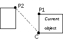
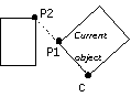
q Rotate an object in view to align one point of it with the rotation center and one point selected in the scene.
You will select:
· An object to be rotated
· The rotation center “C”
· A point “P1” to be aligned (“P1” belongs to the current object)
· A point “P2” (anywhere in the scene) which with “C” will define the alignment line.
|
|
Before alignment |
After alignment |
Usage:
1. Select the element or the part of the element you want to rotate.
Click with the Wand on the element you want to rotate.
If you only want to rotate a part of the element, use the Lasso and the Bullseye selection tools. (See User Manual/Assistant Palette/Selection tools.)
2. Selecting the Rotation tool.
Click on the icon depicting the Rotation tool in the Tools Palette.
A circle appears around the selected element or around the selected part of the element.
3. Dynamic Geometry properties
Depending on how you created the current object, you can work with its Dynamic Geometry properties. This means that you can work on one of the following four finishing levels:
1 – Rough structure
2 – Smoothed structure
3 – Rough object
4 – Smoothed object
In the “Dynamic Geometry” palette, click on the icon depicting the finishing level on which you want to work.
![]()
If you decide to work on your model at finishing level “n”, then you will no longer be able to work on levels “1” to “n-1” (the icon of the disabled levels will disappear).
![]()
For more information, see the chapter User Manual/ The Objects / Dynamic Geometry.
4. Changing the plane of rotation (optional).
You can change the plane of rotation. Use the arrow keys of the numeric keypad to change the plane. (See chapter User Manual/ Modeling help tools/Control Panel/Views).
The circle of rotation is displayed on the selected plane.
The axis of rotation is always perpendicular to the plane of rotation.
5. Defining the center of rotation.
The center of rotation is set by default on the center of geometry of the element.
It is identified by the following icon: ![]()
You can define a different center of rotation:
· 1st method: Click on the corresponding icon in the Assistant Palette.
· 2nd method:
· On PC: Click the right mouse button.
Or
· On Mac: Click the mouse button and simultaneously press the Option key.
The cursor switches to the following shape: ![]()
Click on the new position. The center of rotation will be set on to the nearest existing point of the scene.
6. Alignment.
· Select the point “P1” as follows: hold the Shift key pressed and click on any point of the current object
· Select the point “P2” as follows: hold the Shift key pressed and click again on any point of any object of the scene. Amapi 3D will align the two points.
7. Ending the tool action.
Put the tool aside to end the action (depending on the interface). See chapter User Manual/Tools/Generic use of a tool/How do you end a tool action?